PDFWAC 296-54-565
Intermediate support trees.
(1) Trees used as intermediate supports must be sound and straight from the ground to the point of strap attachment; and must be rigged so that:
(a) Carriage clearance, as measured at the base of the support tree(s) is approximately five feet.
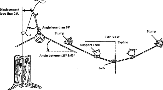
(b) The jackline/support line (see Figure 21: Critical Measurements of the Double Tree Intermediate Support System) is a single piece of line that is one-eighth inch larger than the tong or skidding line or rigged to provide a strength equal to a line one-eighth inch larger than the tong or skidding line.
(2) Vertical support trees must be firmly rooted.
(3) The base of all leaning tree supports must be prevented from moving by:
(a) Retaining twenty percent of the stump diameter in holding wood; or
(b) Other suitable rigging arrangements.
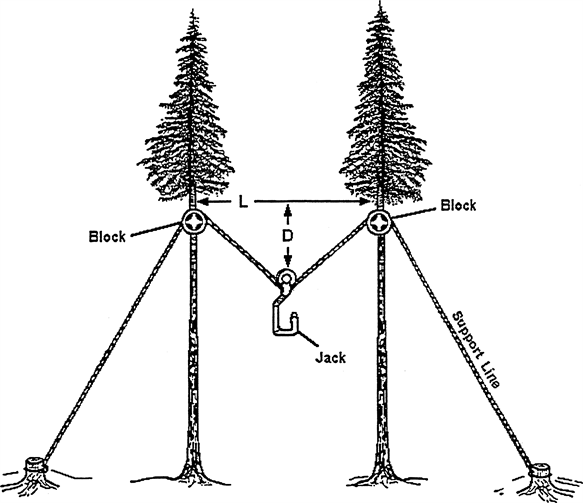
(4) Double tree supports must be rigged so that (see Figure 22: Double Tree Intermediate Support System):
(a) The minimum and maximum heights of the jack relative to the height of the block are as shown below:
(b) The angle the block line makes with the center line of the support tree is as follows:
(i) For skylines one and one-eighth inch and smaller, ten degrees in any direction; and
(ii) For skylines larger than one and one-eighth inch, deflection of the block is in the direction of the jack and a maximum of ten degrees.
(c) The loaded support tree does not displace more than two feet at the point of rigging attachment.
(5) Intermediate support trees must be adequately guyed to withstand any stress to which the tree may be subjected.
(6) Single tree supports must be guyed as follows:
(a) For skylines one and one-eighth inch and less, as shown in Figure 4; and
(b) For skylines larger than one and one-eighth inch, as shown in Figure 6.
(7) Double tree supports must be guyed as follows:
(a) For skylines one and one-eighth inch and less, no guys are required;
(b) For skylines larger than one and one-eighth inch, as shown in Figure 4.
(8) Guylines for intermediate support trees may be made of synthetic material and must be used according to the manufacturer's recommendations.
critical measurements of the double tree intermediate support system
 |
Figure 21: Critical Measurements of the Double Tree Intermediate Support System |
double tree intermediate support system
 |
Front View D = .25 X L = minimum distance D = .5 X L = maximum distance Figure 22: Double Tree Intermediate Support System |
[Statutory Authority: RCW 49.17.010, [49.17].040 and [49.17].050. WSR 99-17-117, § 296-54-565, filed 8/18/99, effective 12/1/99. Statutory Authority: RCW 49.17.040, [49.17].050 and [49.17].060. WSR 96-22-013, § 296-54-565, filed 10/28/96, effective 1/1/97. Statutory Authority: RCW 49.17.040, 49.17.150 and 49.17.240. WSR 79-10-081 (Order 79-14), § 296-54-565, filed 9/21/79.]