
PDFWAC 296-155-960
Protective frame (ROPS) test procedures and performance requirements for wheel-type agricultural and industrial tractors used in construction.
(1) Definitions applicable to this section. Agricultural tractor. As defined by SAE J333a, Operator Protection for Wheel-Type Agricultural and Industrial Tractors (July 1970), a "wheel-type vehicle of more than 20 engine horsepower designed to furnish the power to pull, carry, propel, or drive implements that are designed for agricultural usage." Since this chapter applies only to construction work, the following definition of "agricultural tractor" is adopted for purposes of this part: "Agricultural tractor" means a wheel-type vehicle of more than 20 engine horsepower, used in construction work, which is designed to furnish the power to pull, propel, or drive implements.
Industrial tractor. That class of wheeled type tractor of more than 20 engine horsepower (other than rubber-tired loaders and dozers described in WAC 296-155-955), used in operations such as landscaping, construction services, loading, digging, grounds keeping, and highway maintenance.
• The following symbols, terms, and explanations apply to this section:
Eis | = | Energy input to be absorbed during side loading. Eis = 723 + 0.4 W ft.-lb. (E'is = 100 + 0.12 W', m.- kg). |
Eir | = | Energy input to be absorbed during rear loading. Eir = 0.47 W ft.- lb. (E'ir = 0.14 W', m.- kg). |
W | = | Tractor weight as prescribed in WAC 296-155-960 (5)(a) and (5)(c) in lb. (W', kg). |
L | = | Static load, lb. (kg.). |
D | = | Deflection under L, in. (mm.). |
L-D | = | Static load-deflection diagram. |
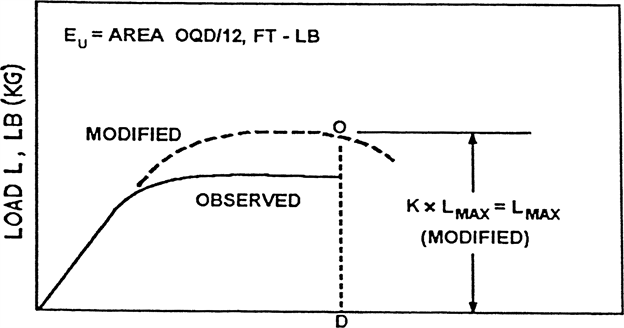
Lm-Dm | = | Modified static load-deflection diagram (Figure V-20). To account for increase in strength due to increase in strain rate, raise L in plastic range to L x K. |
K | = | Increase in yield strength induced by higher rate of loading (1.3 for hot rolled low carbon steel 1010-1030). Low carbon is preferable; however, if higher carbon or other material is used, K must be determined in the laboratory. Refer to Charles H. Norris, et al., Structural Design for Dynamic Loads (1959), p. 3. |
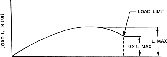
Lmax | = | Maximum observed static load. |
Load limit | = | Point on L-D curve where observed static load is 0.8 Lmax (refer to Figure V-19). |
Eu | = | Strain energy absorbed by the frame, ft.-lb. (m. - kg) area under Lm-Dm curve. |
FER | = | Factor of energy ratio, FER = Eu/Eis; also = Eu/Eir. |
Pb | = | Maximum observed force in mounting connection under static load, L, lb. (kg.). |
FSB | = | Design margin for mounting connection FSB = (Pu/Pb)-1. |
H | = | Vertical height of lift of 4,410 lb. (2,000 kg.) weight, in. (H', mm.). The weight must be pulled back so that the height of its center of gravity above the point of impact is defined as follows: H = 4.92 + 0.00190 W or (H' = 125 = 0.107 W') (Figure V-14). |
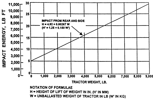 |
FIGURE V-14
Impact energy and corresponding lift height of 4,410 lb. (2,000 kg.) weight.
Note: The standard in this section is derived from, and restates, Society of Automotive Engineers Standard J334a (July 1970), Protective Frame Test Procedures and Performance Requirements. This standard must be used in the event that questions of interpretation arise. The standard appears in the 1971 SAE Handbook.
(2) General.
(a) The purpose of this section is to set forth requirements for frames for the protection of operators of wheel type agricultural and industrial tractors to minimize the possibility of operator injury resulting from accidental upsets during normal operation. With respect to agricultural and industrial tractors, the provisions of WAC 296-155-955 and 296-155-965 for rubber-tired dozers and rubber-tired loaders may be utilized in lieu of the requirements of this section.
(b) The protective frame which is the subject of this standard is a structure mounted to the tractor that extends above the operator's seat and conforms generally to Figure V-15.
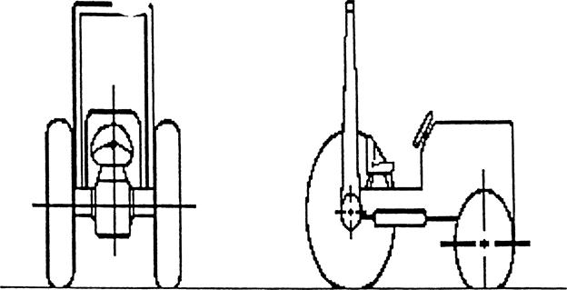 |
FIGURE V-15
Typical frame configuration.
(c) If an overhead weather shield is attached to the protective frame, it may be in place during tests: Provided, That it does not contribute to the strength of the protective frame. If such an overhead weather shield is attached, it must meet the requirements of subsection (10) of this section.
(d) For overhead protection requirements, see WAC 296-155-965.
(e) If protective enclosures are used on wheel-type agricultural and industrial tractors, they must meet the requirements of Society of Automotive Engineers Standard J168 (July 1970), Protective Enclosures, Test Procedures, and performance requirements.
(3) Applicability. The requirements of this section apply to wheel-type agricultural tractors use in construction work and to wheel-type industrial tractors used in construction work. See subsection (1) of this section for definitions of agricultural tractors and industrial tractors.
(4) Performance requirements.
(a) Either a laboratory test or a field test is required in order to determine the performance requirements set forth in subsection (10) of this section.
(b) A laboratory test may be either static or dynamic. The laboratory test must be under conditions of repeatable and controlled loading in order to permit analysis of the protective frame.
(c) You must conduct a field upset test, if used, under reasonably controlled conditions, both rearward and sideways, to verify the effectiveness of the protective frame under actual dynamic conditions.
(5) Test procedure - General.
(a) The tractor used must be the tractor with the greatest weight on which the protective frame is to be used.
(b) You must use a new protective frame and mounting connections of the same design for each test procedure.
(c) You must measure and record instantaneous and permanent frame deformation for each segment of the test.
(d) You must determine dimensions relative to the seat with the seat unloaded and adjusted to its highest and most rearward latched position provided for a seated operator.
(e) If the seat is offset, the frame loading must be on the side with the least space between the centerline of the seat and the upright.
(f) The low temperature impact strength of the material used in the protective structure must be verified by suitable material tests or material certifications in accordance with WAC 296-155-955 (7)(b)(iv).
(6) Test procedure for vehicle overturn.
(a) Vehicle weight. The weight of the tractor, for purposes of this section, includes the protective frame, all fuels, and other components required for normal use of the tractor. You must add ballast if necessary to achieve a minimum total weight of 130 lb. (59 kg.) per maximum power takeoff horsepower at rated engine speed. The weight of the front end must be at least 33 lb. (15 kg.) per maximum power takeoff horsepower. In case power takeoff horsepower is unavailable, you must use 95 percent of net engine flywheel horsepower.
(b) You must test agricultural tractors at the weight set forth in subdivision (a) of this subsection.
(c) You must test industrial tractors with items of integral or mounted equipment and ballast that are sold as standard equipment or approved by the vehicle manufacturer for use with the vehicle where the protective frame is expected to provide protection for the operator with such equipment installed. The total vehicle weight and front end weight as tested must not be less than the weights established in subdivision (a) of this subsection.
(d) You must conduct the test on a dry, firm soil bank as illustrated in Figure V-16. The soil in the impact area must have an average cone index in the 0.6 in. (153 mm.) layer not less than 150 according to American Society of Agricultural Engineers Recommendations ASAE R313, Soil Cone Penetrometer. The path of travel of the vehicle must be 12° ± 2° to the top edge of the bank.
(e) The upper edge of the bank must be equipped with an 18 in. (457 mm.) high ramp as described in Figure V-16 to assist in tipping the vehicle.
(f) The front and rear wheel tread settings, where adjustable, must be at the position nearest to halfway between the minimum and maximum settings obtainable on the vehicle. Where only two settings are obtainable, you must use the minimum setting.
(g) Vehicle overturn test - Sideways and rearward.
(i) You must drive the tractor under its own power along the specified path of travel at a minimum speed of 10 m.p.h. (16 km./hr.) or maximum vehicle speed if under 10 m.p.h. (16 km./hr.) up the ramp as described in subdivision (e) of this subsection to induce sideways overturn.
(ii) Rear upset must be induced by engine power with the tractor operating in gear to obtain 3-5 m.p.h. (4.8-8 km./hr.) at maximum governed engine r.p.m. preferably by driving forward directly up a minimum slope of two vertical to one horizontal. The engine clutch may be used to aid in inducing the upset.
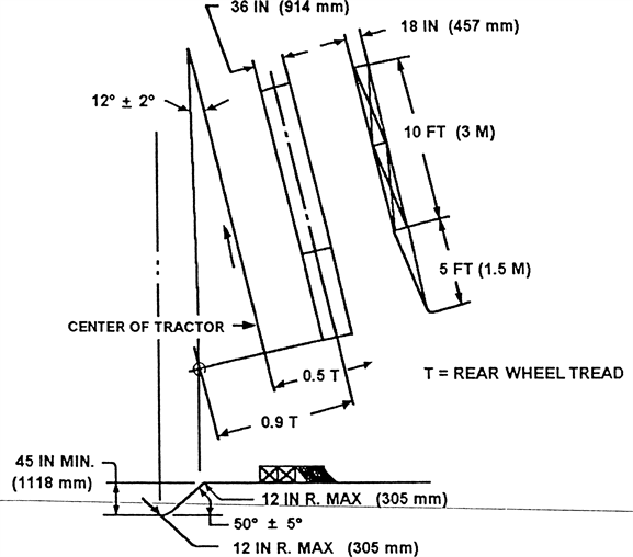 |
FIGURE V-16
(7) Other test procedures. When the field upset test is not used to determine ROPS performance, you must perform either the static test or the dynamic test, contained in subsection (8) or (9) of this section.
(8) Static test.
(a) Test conditions.
(i) The laboratory mounting base must include that part of the tractor chassis to which the protective frame is attached including the mounting parts.
(ii) The protective frame must be instrumented with the necessary equipment to obtain the required load deflection data at the locations and directions specified in Figures V-17, V-18, and V-19.
 |
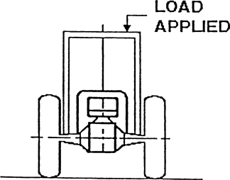 |
FIGURE V-17
Side load application.
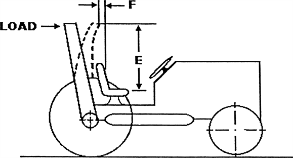 |
FIGURE V-18
Rear load application.
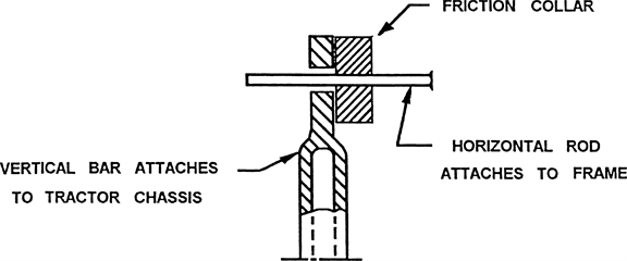 |
FIGURE V-19
Method of measuring instantaneous deflection.
(iii) The protective frame and mounting connections must be instrumented with the necessary recording equipment to obtain the required load-deflection data to be used in calculating FSB (see subsection (1)(c) of this section). The gauges must be placed on mounting connections before the installation load is applied.
(b) Test procedure.
(i) The side load application must be at the upper extremity of the frame upright at a 90° angle to the centerline of the vehicle. The side load "L" must be applied according to Figure V-17. "L" and "D" must be recorded simultaneously. You must stop the test when:
(A) The strain energy absorbed by the frame is equal to the required input energy (Eis); or
(B) Deflection of the frame exceeds the allowable deflection; or
(C) The frame load limit occurs before the allowable deflection is reached in the side load.
(ii) You must construct the L-D diagram, as shown by means of a typical example in Figure V-20, using the data obtained in accordance with item (i) of this subdivision.
(iii) You must construct the modified Lm-Dm diagram according to item (ii) of this subdivision and according to Figure V-21. You must then determine the strain energy absorbed by the frame (Eu).
(iv) You must calculate Eis, FER and FSB.
 |
deflection d, in (mm) |
FIGURE V-20
Typical L-D diagram.
 |
deflection d, in (mm) |
FIGURE V-21
Typical modified Lm-Dm diagram.
(v) You must repeat the test procedure on the same frame utilizing L (rear input; see Figure V-19) and Eir. Rear load application must be uniformly distributed along a maximum projected dimension of 27 in. (686 mm.) and a maximum area of 160 sq. in. (1,032 sq. cm.) normal to the direction of load application. You must apply the load to the upper extremity of the frame at the point which is midway between the centerline of the seat and the inside of the frame upright.
(9) Dynamic test.
(a) Test conditions.
(i) The protective frame and tractor must meet the requirements of subsection (6)(b) or (c) of this section, as appropriate.
(ii) The dynamic loading must be produced by use of a 4,410 lb. (2,000 kg.) weight acting as a pendulum. The impact face of the weight must be 27 plus or minus one inch by 27 plus or minus one inch (686 + or - 25 mm.) and must be constructed so that its center of gravity is within one inch (25.4 mm.) of its geometric center. The weight must be suspended from a pivot point 18-22 ft. (5.5-6.7 m.) above the point of impact on the frame and must be conveniently and safely adjustable for height. (See Figure V-22.)
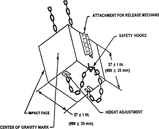 |
FIGURE V-22
Pendulum.
(iii) For each phase of testing, you must restrain the tractor from moving when the dynamic load is applied. The restraining members must be of 0.5-0.63 in. (12.5-16 mm.) steel cable and points of attaching restraining members must be located an appropriate distance behind the rear axle and in front of the front axle to provide a 15°-30° angle between a restraining cable and the horizontal. The restraining member must either be in the plane in which the center gravity of the pendulum will swing or more than one restraining cable must give a resultant force in this plane. (See Figure V-23.)
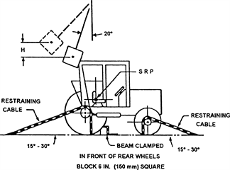 |
FIGURE V-23
Method of impact from rear.
(iv) The wheel tread setting must comply with the requirements of subsection (6)(f) of this section. The tires must have no liquid ballast and must be inflated to the maximum operating pressure recommended by the tire manufacturer. With specified tire inflation, the restraining cables must be tightened to provide tire deflection of 6-8 percent of nominal tire section width. After the vehicle is properly restrained, a wooden beam 6 x 6 in. (15 x 15 cm.) must be driven tightly against the appropriate wheels and clamped. For the test to the side, an additional wooden beam must be placed as a prop against the wheel nearest the operator's station and must be secured to the floor so that it is held tightly against the wheel rim during impact. The length of this beam must be chosen so that when it is positioned against the wheel rim it is at an angle of 25°-40° to the horizontal. It must have a length 20-25 times its depth and a width two to 3 times its depth. (See Figures V-23 and V-24.)
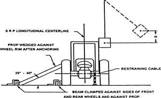 |
FIGURE V-24
Method of impact from side.
(v) You must provide means indicating the maximum instantaneous deflection along the line of impact. A simple friction device is illustrated in Figure V-24.
(vi) No repair or adjustments may be carried out during the test.
(vii) If any cables, props, or blocking shift or break during the test, you must repeat the test.
(b) Test procedure.
(i) General. You must evaluate the frame by imposing dynamic loading to rear followed by a load to the side on the same frame. The pendulum dropped from the height (see definition "H" in subsection (1)(c) of this section) imposes the dynamic load. You must select the position of the pendulum so that the initial point of impact on the frame is in line with the arc of travel of the center of gravity of the pendulum. You should use a quick release mechanism but, if used, it must not influence the attitude of the block.
(ii) Impact at rear. You must properly restrain the tractor according to subdivisions (a)(iii) and (iv) of this section. You must position the tractor with respect to the pivot point of the pendulum such that the pendulum is 20° from the vertical prior to impact, as shown in Figure V-23. The impact must be applied to the upper extremity of the frame at the point which is midway between the centerline of the seat and the inside of the frame upright of a new frame.
(iii) Impact at side. The block and restraining must conform to subdivisions (a)(iii) and (iv) of this subsection. The point of impact must be that structural member of the protective frame likely to hit the ground first in a sideways accidental upset. The side impact must be applied to the side opposite that used for rear impact.
(10) Performance requirements.
(a) General.
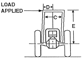
(i) The frame, overhead weather shield, fenders, or other parts in the operator area may be deformed but must not shatter or leave sharp edges exposed to the operator, or violate dimensions as shown in Figures V-17 and V-18 as follows:
D | = | 2 in. (51 mm.) inside of frame upright to vertical centerline of seat. |
E | = | 30 in. (762 mm.). |
F | = | Not less than 0 in. and not more than 12 in. (305 mm.), measured at centerline front of seat backrest to crossbar along the line of load application as shown in Figure V-17. |
G | = | 24 in. (610 mm.). |
(ii) The material and design combination used in the protective structure must be such that the structure can meet all prescribed performance tests at zero degrees Fahrenheit in accordance with WAC 296-155-955 (7)(b)(iv).
(b) Vehicle overturn performance requirements. You must meet the requirements of this subsection (10) in both side and rear overturns.
(c) Static test performance requirements. Design factors must be incorporated in each design to withstand an overturn test as prescribed in this subsection (10). The structural requirements will be generally met if FER is greater than one and FSB is greater than K-1 in both side and rear loadings.
(d) Dynamic test performance requirements. Design factors must be incorporated in each design to withstand the overturn test prescribed in this subsection (10). The structural requirements will be generally met if the dimensions in this subsection (10) are adhered to in both side and rear loads.
[Statutory Authority: RCW 49.17.010, 49.17.040, 49.17.050, 49.17.060. WSR 16-09-085, § 296-155-960, filed 4/19/16, effective 5/20/16. Statutory Authority: RCW 49.17.010, [49.17].040, [49.17].050. WSR 02-12-098, § 296-155-960, filed 6/5/02, effective 8/1/02; Order 74-26, § 296-155-960, filed 5/7/74, effective 6/6/74.]